- Details
Rinehart Inverter PM100DX Installation
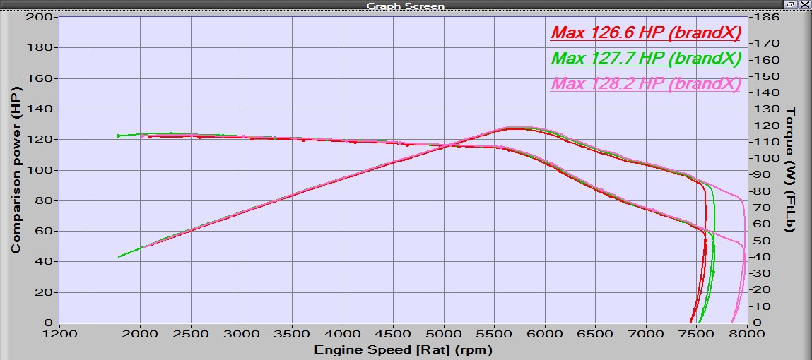
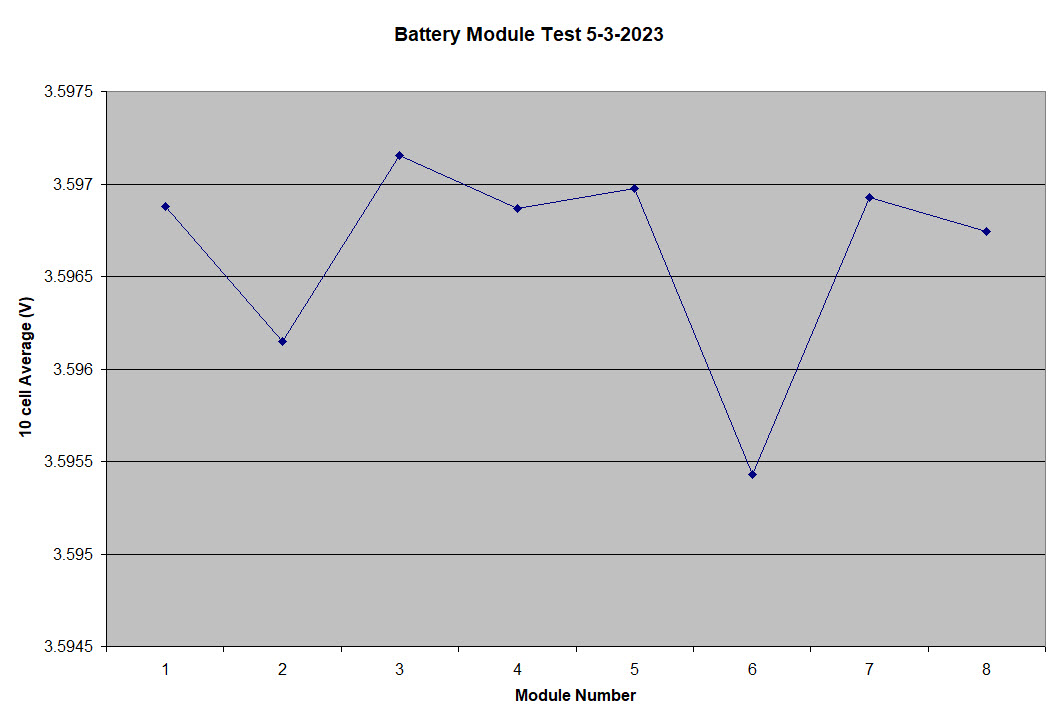
I replaced the DMOC/GEVCU inverter and controller with a Scott Drive SD100 (See Blog below Scott Drive Installation) because the GEVCU controller was having reliability issues. The Scott Drive proved to be very reliable once the setup was completed. The SD100 has many great features, including a built-in precharge circuit and isolation switch. It provides all the CAN message for the motor performance and has a GUI for setup, calibration and control. The SD100 showed much better reliability and seemed to perform well - i.e. the car seemed to accelerate well. Something that I never did for the DMOC/GEVCU setup was to run the car on a dynamometer to measure the power and torque output. The only benchmark for the DMOC/GEVCU - Siemens motor setup was in a 1978 VW Thing, that was measured to have 160HP and 221 ft-lb of torque. Last summer I found a nearby shop that had several dynamometers and was able to get the 320e tested with the Scott Drive. I was not expecting a great result as I had measured that the Scott Drive was outputting high power, but only for 3 seconds. That is hardly enough time to accelerate the car, although it is something you can definitely feel in the seat of you pants. Unfortunately, the SD100 really is not accelerating the car and was such a problem when testing on the dynamometer that in first gear the wheels would not even turn. The car would just lurch on its suspension and then settle. The Scott Drive shuts down the current to less than half of full current after 3 seconds, even with the accelerator pedal pressed to the floor. The best HP/Torque curve was obtained in 3rd gear, but is very disappointing. See the graph below.
Power torque curve for the 320e in third gear with the SD100.The max power is 128HP and the max torque only 110ft-lb.
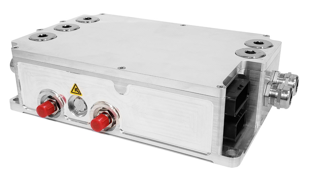
This poor power/torque performance was expected based on how the current shuts down from the inverter. There is no adjustment on that parameter, it is built into the firmware and the maker of Scott Drive does not give access to changing firmware values. I think Scott Drive does not know how to use their inverters in a car application. The only data I had seen from them was bench testing. That provides a minimal look at the performance. But it seem like their only goal is to over protect the Integrated Gate Bipolar Transistors (IGBT)s. There is no warranty on this inverter. It is more than 6 years old, so why should Scott Drive care how hard I drive the IGBTs? This issue is what convinced me to change to a Rinehart Inverter. The first parameter I looked at for the Rinehart was the current – time limit. Cascadia Motion (who own Rinehart) say in their documentation to limit the full current of 350Amp RMS to less than 30 seconds!!! Also, from the documentation is seems like most of the firmware is open – i.e., most of the parameters are adjustable. This should work much better for driving the 320e and the documentation for the Rinehart shows that Scott Drive is wrong about driving IGBTs. The small downside of the Rinehart is there is no GUI for setup and calibration. Those values all have to be entered into the firmware via a GUI that has access to every paramter, but no auto process for calibration. It is all by procedure. Below is an image of the Rinehart PM100DX inverter.
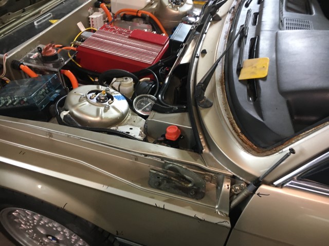
All of the high current DC and AC wires and the water lines are the same as the SD100. The biggest difference is the analog and logic connections to the controller. The PM100DX has Ampseal 35pin and Ampseal 23pin connectors for all those functions. Ampseal is actually an easier connector to work with than what was on the SD100 and most of the car uses Ampseal connectors. Because of the new connector system I had to build a whole new wiring harness and changed most of the connections in my wire crossover box. The PM100DX is a different size than the SD100 so I had to cut some aluminum plates to make an adapter to the DMOC frame, that sits on top of the Siemens motor. Because the Rinehart is considerably smaller than the SD100 I installed a couple of carbon fiber plates to cover the open areas above the Siemens Motor. Control of the Rinehart is very similar to the SD100, the major difference is the logic reference. For the SD100 logic was positive (i.e. +5V switching) but on the Rinehart the logic is ground switching. To use the same wires I already had installed in the glove box I had to verify that all the logic wires were isolated so I could just swap the connections. The only wire I had a problem with was the USB connector for phone charging. I had to grab a +12V and ground from under the dash to power that connection.
As soon as it is warm enough to drive the car (still has summer tires installed) I will schedule a session on the dynamometer and post a blog with those results.
A video of the PM100DX installation will be available soon.
- Details
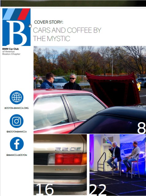
Cars and Coffee By the Mystic
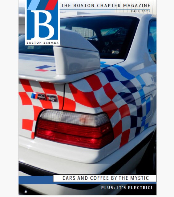
Now that the 320e has new batteries and has been repainted I started taking it to car shows to show it off. One of the shows I attended was the Cars and Coffee at the Mystic River BMW dealer. That was on 11/14/2021 and it was just warm enough that day to drive the car. The organizer of the Boston Chapter of the BMWCCA was so impressed with my car that he asked me to write and article about the conversion process, that they would publish in the online magazine about the event. You can see the cover image and the tile page for my article below. The complete pdf can be found here: Boston Cars and Coffee.
.

- Details
Battery Maintenance System (BMS)
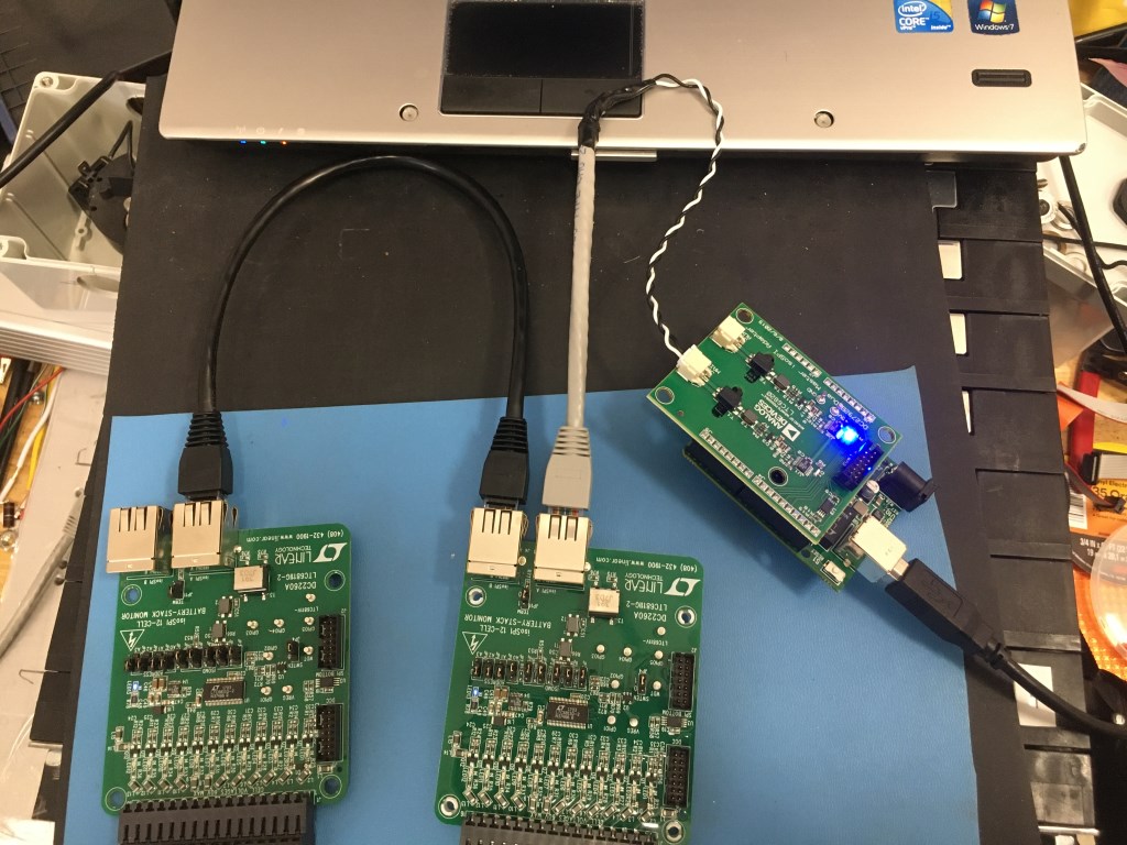
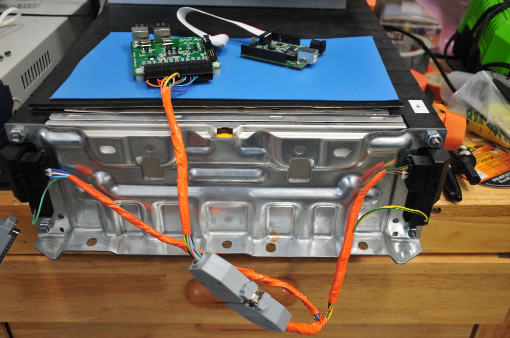
Initially the Battery Maintenance System (BMS) will be provided by the Analog Devices DC2259A BMS Demo board which demonstrates the LTC6811-1 BMS integrated circuit. This circuit has the ability to measure 12 battery cells simultaneously and communicate via standard SPI. The demo board is connected to a Linduino with a 14-pin ribbon cable. The Linduino is Analog Devices version an Arduino Uno and is required to communicate with any of the Analog Devices demo boards. Standard SPI is used to communicate between the Linduino and the demo board. The D2259A demo boards are somewhat expensive ($150 +S&H) plus the cost of the Linduino ($125) and DC2292B ($75) shields (9 demo boards plus 2 Linduino and 2 DC2292B would be needed). Plus an overall controlling circuit needs to be designed to take the data on the from the Linduinos on the IsoSPI connection. A new circuit based on the DC2260A has been designed and the initial build started. The DC2260A has the same battery monitoring circuity as the DC2259A but uses the LTC6811-2 BMS integrated circuit. My BMS design will use the LTC6811-2. The new circuit design incorporates an Arduino Nano Every processor and an isolated CAN BUS interface. The Nano communicates with the LTC6811-2 to read the cell voltages and then sends that data out on the CAN BUS. A much cheaper implementation (almost one-third the price) and there already is a CAN BUS system in the car the controls the dashboard instruments. Probably the first 4 battery modules will be used with the DC2260A BMS demo boards and the other battery modules in the car will be monitored with my circuit design. The design of the new PCA can be seen (here).
The screen picture below shows the Multicell Monitor GUI during the discharge process. In normal operation in the car, only cells that are at a higher voltage would be discharged. An algorithm will be written to control that process.
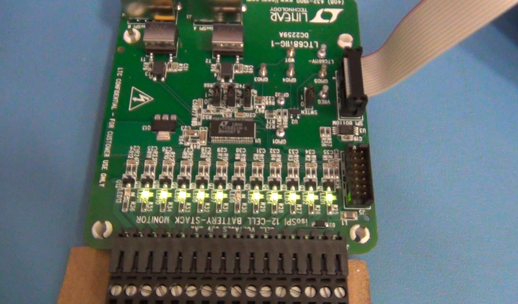
Top side of DC2259A BMS Demo board showing active discharge channels. When the MOSFETs are turned on to discharge a battery cell the LEDs light up. Again, 6 and 12 are not lit because they are not connected on the 10 cell battery module.
Bottom of DC2259A showing the discharge resistors. The resistors are 33 ohm so on a battery cell that varies from 3.5V to 4.1V there can only be a little more than 100mA discharge current. On a cell that is 180AH that would take 1800 hrs of time to fully discharge (75 days). This board is not designed for that. The design is to just trim the cell voltages so they are all the same value.
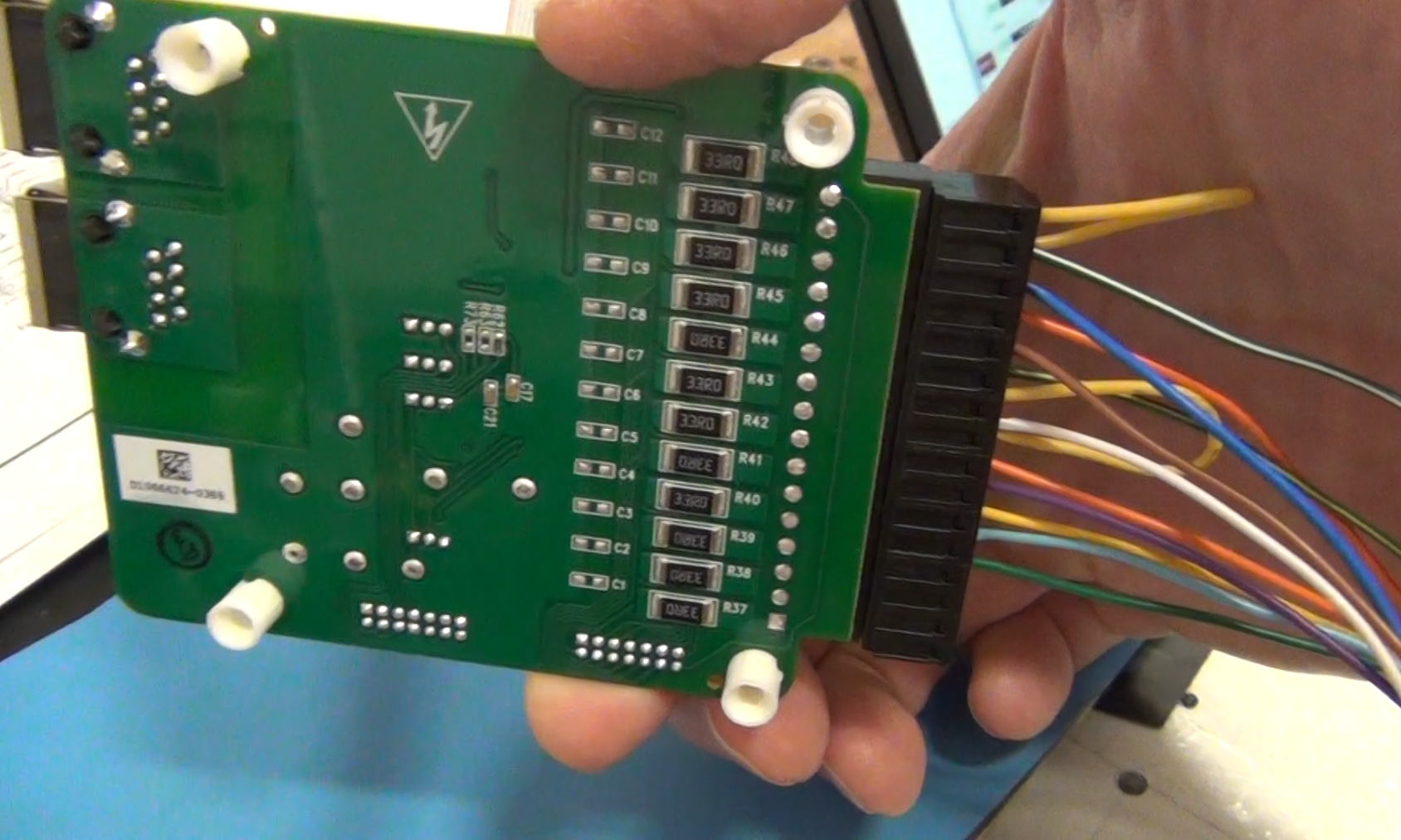
Image below shows the demonstration of the isolated SPI (isoSPI) that can be used to connect up to 5 BMS demo boards to one Linduino and a DC2792B isoSPI shield. In the car there if that system was used there will need to be two Linduino/DC2792B controllers for the 9 Bolt Battery modules. The iosSPI is limited to 5 boards so that is why it would require two Linduinos and DC2792B shields. Initially the IsoSPI will be used for the first 4 batteries and the remaining 5 will use the BMS board of my design with the isolated CAN Bus communication.
- Details
Chevy Bolt Batteries
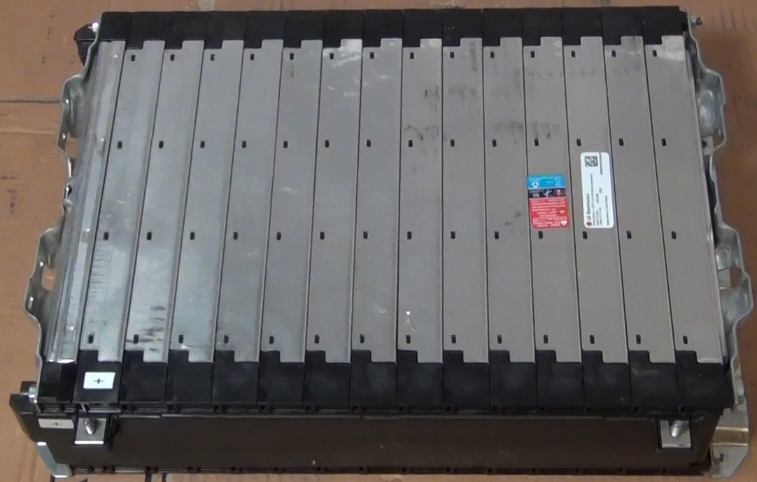
To get more driving range and because many of my original CALIB batteries had degraded, the batteries were upgraded in late 2020. The upgrade batteries that were acquired new are the Chevy Bolt 5.94kW-h module shown in the picture below. These modules are made by LG Electronics and are NCM (Lithium Nickel Cobalt Manganese Oxide) chemistry. Each module has a 180AH capacity and the 9 modules that will be used gives a 53kW-h battery capacity. For a 85% discharge that provides 45kW-h of driving capacity. At the measured power consumption of 292W/mile by the vehicle that capacity should provide just about 155 miles driving range. Although the new batteries are bigger and weigh more than the CALAB cells the new batteries will only increase the weight of the car 100 lbs but increase the driving range by 2 times! A great feature of these modules is that they are already wired for a Battery Maintenance System (BMS). Each module has 10 cells wired in series and there are connections to each cell on the module so the individual battery voltages can be measured. The connections are a pair of multi-pin connectors at one end of the module. The Chevy Bolt uses a central processing unit for the battery maintenance so in the Bolt each battery module has a pair of cables that runs back to the central controller. For my build each battery module will have its own BMS controller. This is easier than running wires from each module up to the engine compartment. Although between the wires from one module the most voltage would be 41V (full charged battery) the wires will have the full pack voltage, with respect to ground. Local BMS control will be safer at this point in the 320e build. I was able to order the Chevy Bolt battery wiring harness on Chevy Parts Online. By taking the wiring harness apart I could build several cables with the corresponding connectors already attached and used them to connect to the local BMS controlling circuit. A BMS demo board, the DC2259B made by Analog Devices was initially tested to use for the module BMS. The connections to the battery module and a BMS demo board are shown in the second and third photos below.
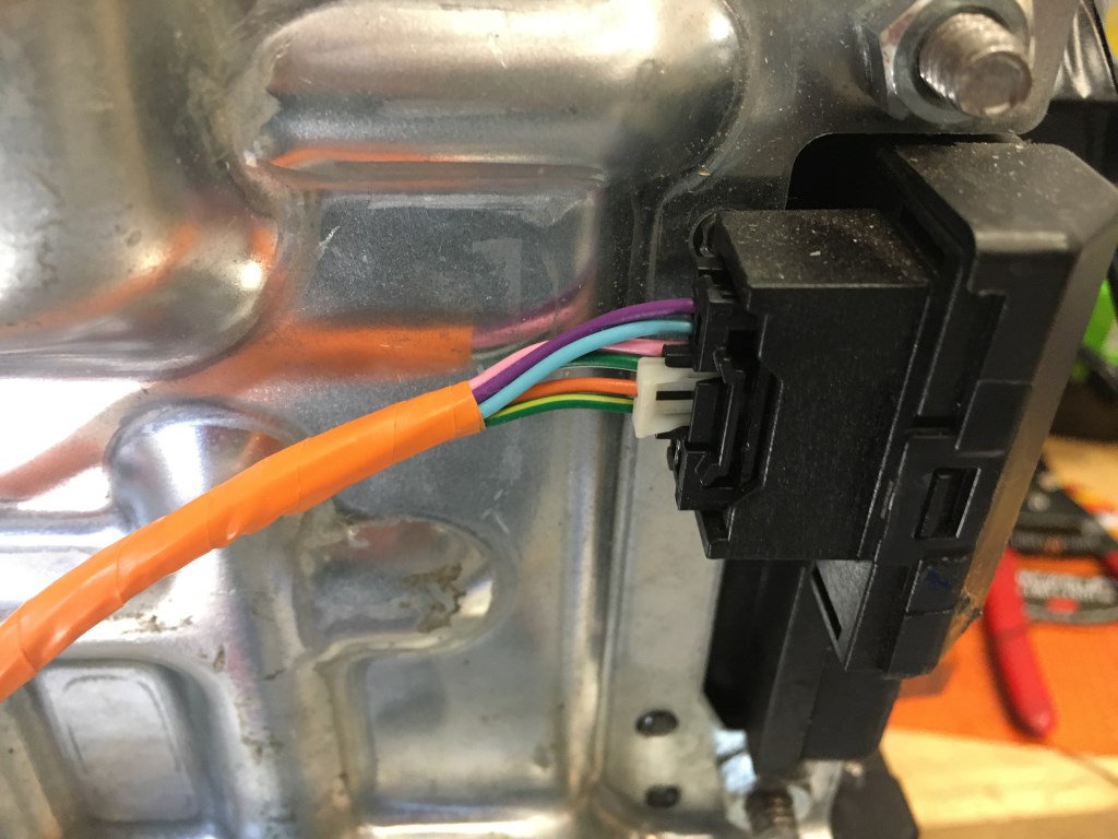
BMS connection on battery module. These connectors were obtain from a Chevy Bolt battery wiring harness that was purchased online. The connectors are keyed and lockable.
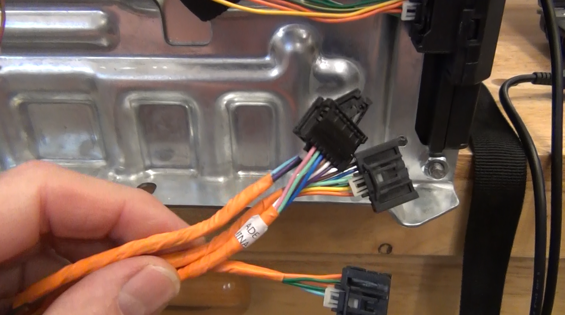
I did not have a wiring diagram of the BMS connections on the Bolt battery module. I assembled a couple of barrier strips and broke out all the wires from each connector to determine which wires were the pairs for each battery cell in the module. I highlighted the connections for the first cell. Using this method allowed me to make a connector to connect the BMS demo board. However, the wiring order had to change for connection to the BMS demo board. True that in the image M11 to M21 is the first cell. For the BMS demo that M21 wire has to be next to the M11 wire (green and cyan). By alternating the wires from each connector the battery voltage steps up for each connection, relative to the battery (-) connection because the cells are all wired in series.
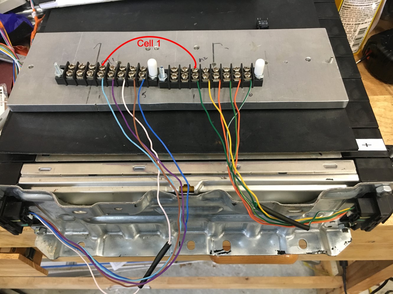
A DB25 connector is used for the wires coming from the battery module to make connection the BMS demo board because the demo board is only supplied with screw connectors. The DB25 was installed on all the modules to enable the test of all the batteries with one DC2259A Demo board.
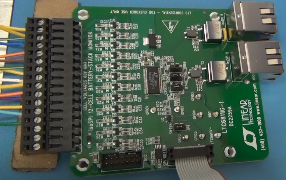
Pictured below the DC2259A BMS demo board that demonstrates the LTC6811-1 BMS integrated circuit. It is the 48-pin integrated circuit at the center of the board. The other components on the board are a set of transistors and resistors for trimming the battery cell voltages and a group of circuits for data communication.
Below is a plot of the average of the ten cells in each battery module that was measured with one DC2259A BMS demo board on 12-21-2020. This measurement is of the as-received modules from the factory. For effectively 90 cells the cell voltage variance is only +/- 2.5mV. If the two modules that show the largest difference we adjusted to match the other modules the variance would drop to +/- 1mV!
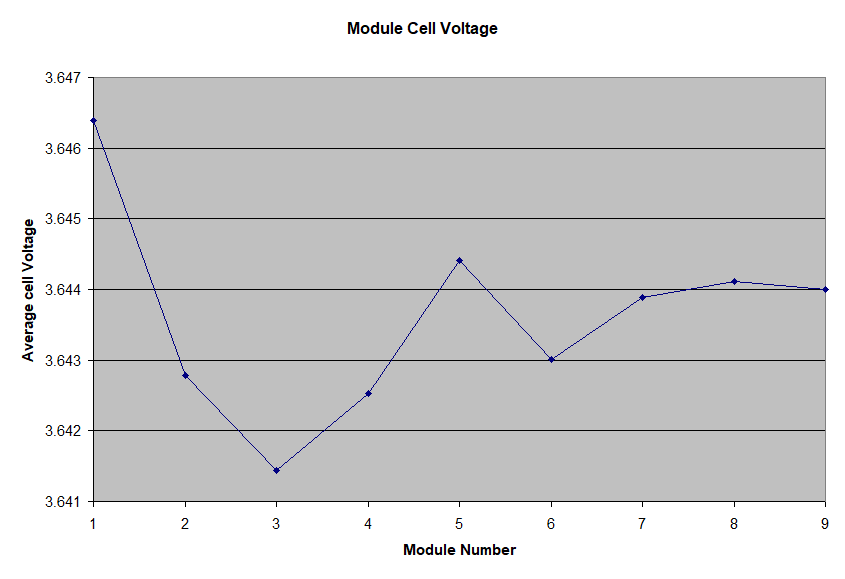
UPDATE: Below is the average cell voltage for 8 of the battery modules, measured recently. The batteries are at a different state of charge (SOC) but the cell voltage distribution is even tighter, less than +/- 1mV. The 9th battery module was not included because it is being used as a bench test platform and the battery box to house the module has not been built yet, so it is not in the car connected to the other battery modules. No adjustment of the individual battery modules was done. This is after nearly three years of charge and discharge cycles.
- Details
Repaint, New All Weather Tires and Wheels
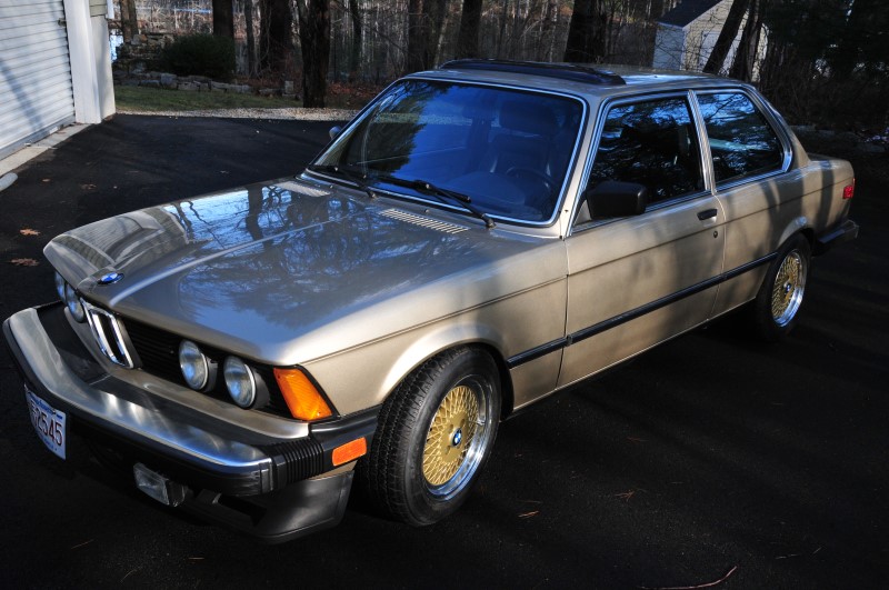
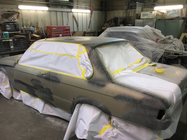
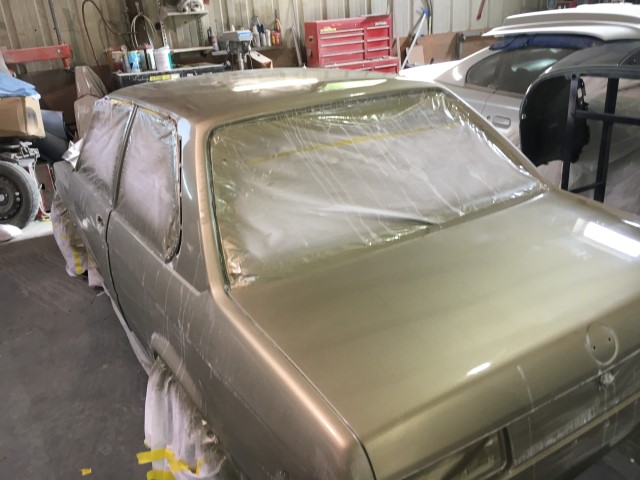
One thing I always wanted to do to the car since I started the conversion was to have it repainted. The paint was still in good condition for original paint. But the roof paint was faded and there were several rust spots around the bottom of the windshield and several dents in the doors. The problem is that the car could not be painted with the CALIB batteries installed. To paint the car all the batteries would need to be removed. That is because during many phases of the painting, the car is in a closed room with an explosive atmosphere - due to the volatile solvents used in painting. One spark could cause a huge explosion. In fact, for a whole car painting like I am having done, the painters usually remove the 12V battery just to eliminate that as a problem. As more and more of the CALIB batteries began to have charging problems (due to too many over-discharges) I decided to have the car painted because I was going to replace the batteries. I removed all the CALAB batteries and had the car towed to the paintshop. The paint job took more than two months, mostly because it was painted during the height of the pandemic. I was however, able to visit the paint shop and take some pictures of the process. Shown below is an image after all the chrome was removed and windshield was removed. The rust that was around the windshield is more apparent. The second image is after all the body work was done and the start of priming. The third image is after the car was fully painted and during the wet sanding process, also known a cutting. That is done to smooth out any imperfections in the paint. Once the wet sanding is done the paint is polished and once all the polishing is completed a clear coat is applied.
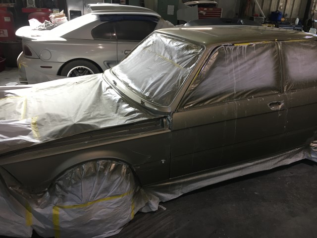
The paint color is not the original BMW color code. I wanted to have more metal flake in the paint. The painter said he could mix some metal flake into the BMW color, but then I would have a custom color that might be hard to replicate, if I ever needed some more paint. So the color is actually for a 2010 Ford F150 pickup truck, a shade I picked out of the color coupons, that matched the BMW color closely. In the sunlight the metal flake in the paint really pops. You can see that in the closeup of the paint in the lower image.
Once I got the painted car home and cleaned up, I wanted to drive the car, but the painting took until mid November to complete. I usually have summer tires mounted on the 320i (Dunlop Direzza) so those cannot be used below 35F. To be able to drive the car in the cold weather I got a set of BF Goodrich T/A Radials, all weather tires and some Enkei ENKEI92 wheels, with a gold insert. The wheels look good with the paintjob and they were much cheaper than the Rial wheels I have with the summer tires. The image below is the car with the new winter tires and wheels