Battery Maintenance System (BMS)
Initially the Battery Maintenance System (BMS) will be provided by the Analog Devices DC2259A BMS Demo board which demonstrates the LTC6811-1 BMS integrated circuit. This circuit has the ability to measure 12 battery cells simultaneously and communicate via standard SPI. The demo board is connected to a Linduino with a 14-pin ribbon cable. The Linduino is Analog Devices version an Arduino Uno and is required to communicate with any of the Analog Devices demo boards. Standard SPI is used to communicate between the Linduino and the demo board. The D2259A demo boards are somewhat expensive ($150 +S&H) plus the cost of the Linduino ($125) and DC2292B ($75) shields (9 demo boards plus 2 Linduino and 2 DC2292B would be needed). Plus an overall controlling circuit needs to be designed to take the data on the from the Linduinos on the IsoSPI connection. A new circuit based on the DC2260A has been designed and the initial build started. The DC2260A has the same battery monitoring circuity as the DC2259A but uses the LTC6811-2 BMS integrated circuit. My BMS design will use the LTC6811-2. The new circuit design incorporates an Arduino Nano Every processor and an isolated CAN BUS interface. The Nano communicates with the LTC6811-2 to read the cell voltages and then sends that data out on the CAN BUS. A much cheaper implementation (almost one-third the price) and there already is a CAN BUS system in the car the controls the dashboard instruments. Probably the first 4 battery modules will be used with the DC2260A BMS demo boards and the other battery modules in the car will be monitored with my circuit design. The design of the new PCA can be seen (here).
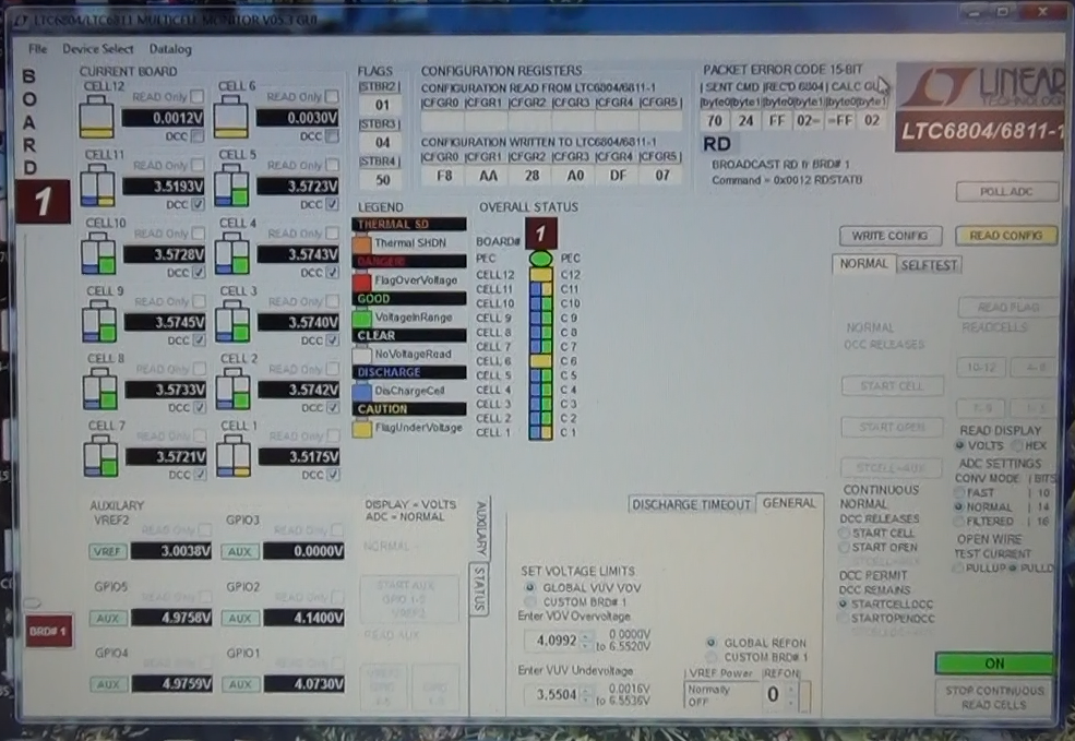
The screen picture below shows the Multicell Monitor GUI during the discharge process. In normal operation in the car, only cells that are at a higher voltage would be discharged. An algorithm will be written to control that process.
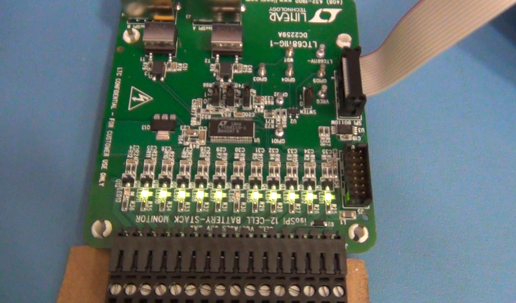
Top side of DC2259A BMS Demo board showing active discharge channels. When the MOSFETs are turned on to discharge a battery cell the LEDs light up. Again, 6 and 12 are not lit because they are not connected on the 10 cell battery module.
Bottom of DC2259A showing the discharge resistors. The resistors are 33 ohm so on a battery cell that varies from 3.5V to 4.1V there can only be a little more than 100mA discharge current. On a cell that is 180AH that would take 1800 hrs of time to fully discharge (75 days). This board is not designed for that. The design is to just trim the cell voltages so they are all the same value.
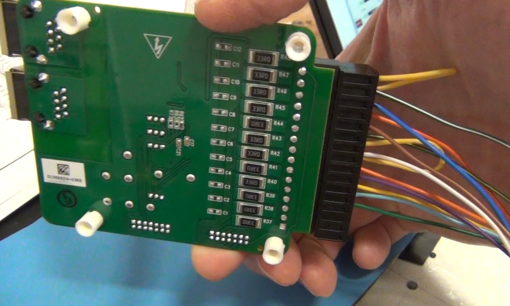
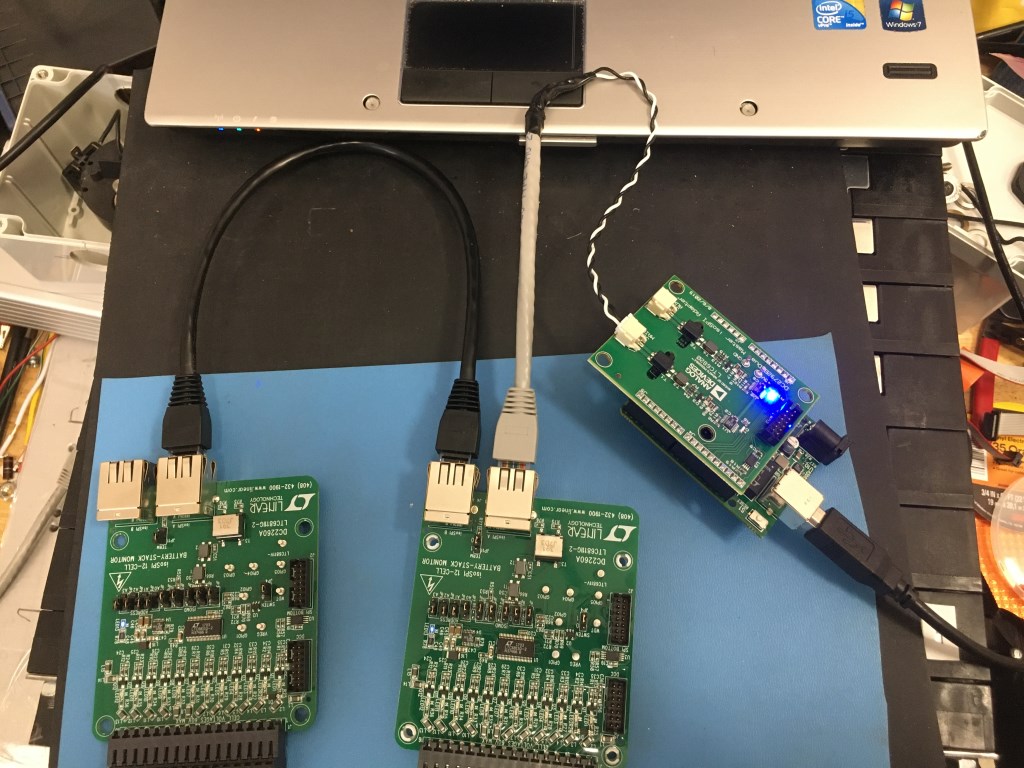
Image below shows the demonstration of the isolated SPI (isoSPI) that can be used to connect up to 5 BMS demo boards to one Linduino and a DC2792B isoSPI shield. In the car there if that system was used there will need to be two Linduino/DC2792B controllers for the 9 Bolt Battery modules. The iosSPI is limited to 5 boards so that is why it would require two Linduinos and DC2792B shields. Initially the IsoSPI will be used for the first 4 batteries and the remaining 5 will use the BMS board of my design with the isolated CAN Bus communication.