Chevy Bolt Batteries
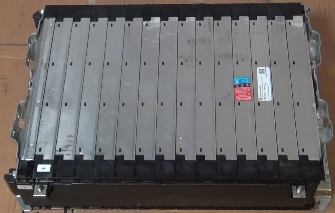
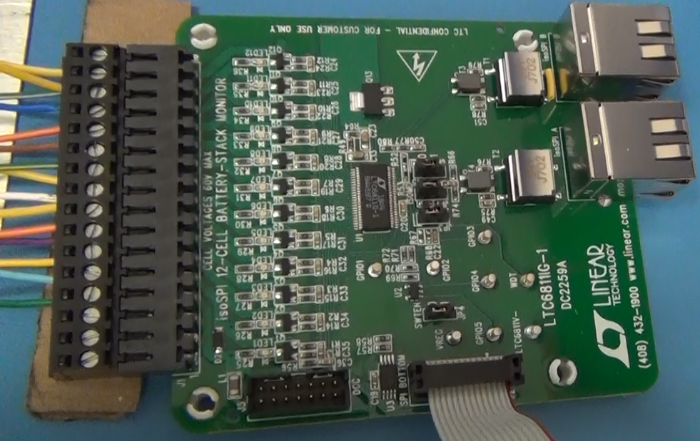
To get more driving range the batteries were upgraded in early 2021. The upgrade batteries used are the Chevy Bolt 5.94kW-h module shown in the picture below. These modules are made by LG Electronics and are NCM (Lithium Nickel Cobalt Manganese Oxide) chemistry. Each module has a 180AH capacity and the 9 modules that will be used gives a 53kW-h battery capacity. For a 85% discharge that provides 45kW-h of driving capacity. At the measured power consumption of 292W/mile by the vehicle that capacity should provide just about 155 miles driving range. A great feature of these modules is that they are already wired for a Battery Maintenance System (BMS). Each module has 10 cells wired in series and there are connections to each cell on the module so the individual battery voltages can be measured. The connections are a pair of multi-pin connectors at one end of the module. The Chevy Bolt uses a central processing unit for the battery maintenance so in the Bolt each battery module has a pair of cables that runs back to the central controller. For my build each battery module will have its own BMS controller. This is easier than running wires from each module up to the engine compartment. Although between the wires from one module the most voltage would be 41V (full charged battery) the wires will have the full pack voltage, with respect to ground. Local BMS control will be safer at this point in the 320e build. I was able to order the Chevy Bolt battery wiring harness on Chevy Parts Online. By taking the wiring harness apart I could build several cables with the corresponding connectors already attached and used them to connect to the local BMS controlling circuit. A BMS demo board, the DC2259B made by Analog Devices was initially tested to use for the module BMS. The connections to the battery module and a BMS demo board are shown in the second and third photos below. Although the new batteries are bigger and weigh more than the CALAB cells the new batteries will only increase the weight of the car 100 lbs but increase the driving range by 2 times!
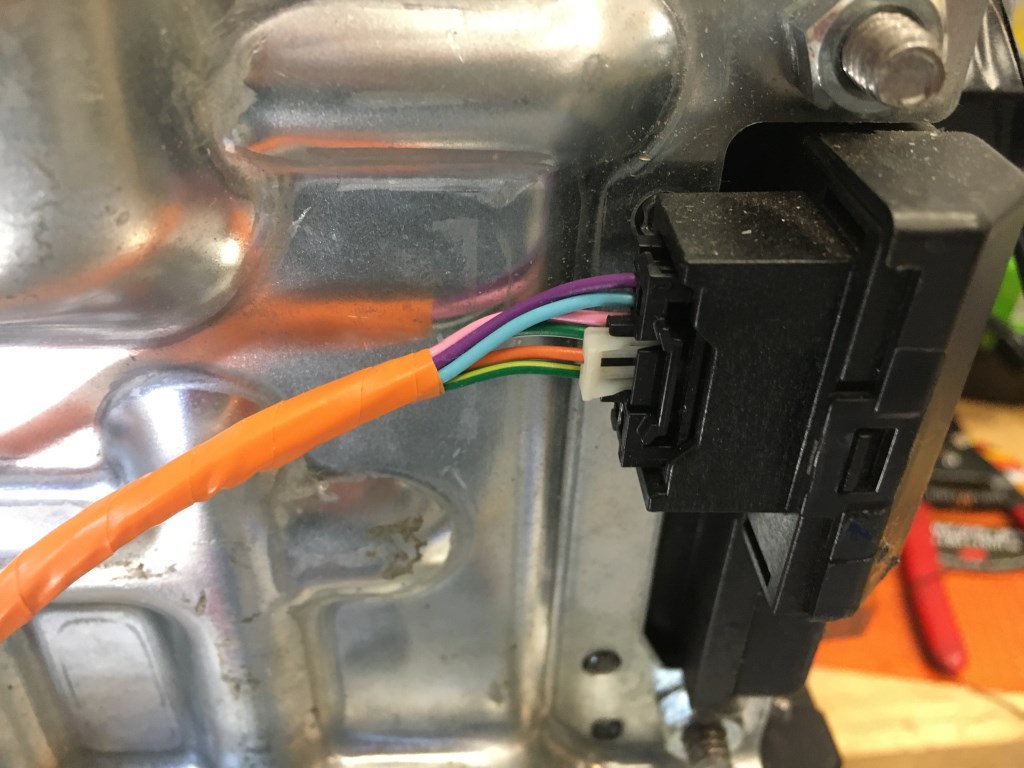
BMS connection on battery module. These connectors were obtain from a Chevy Bolt battery wiring harness that was purchased online.
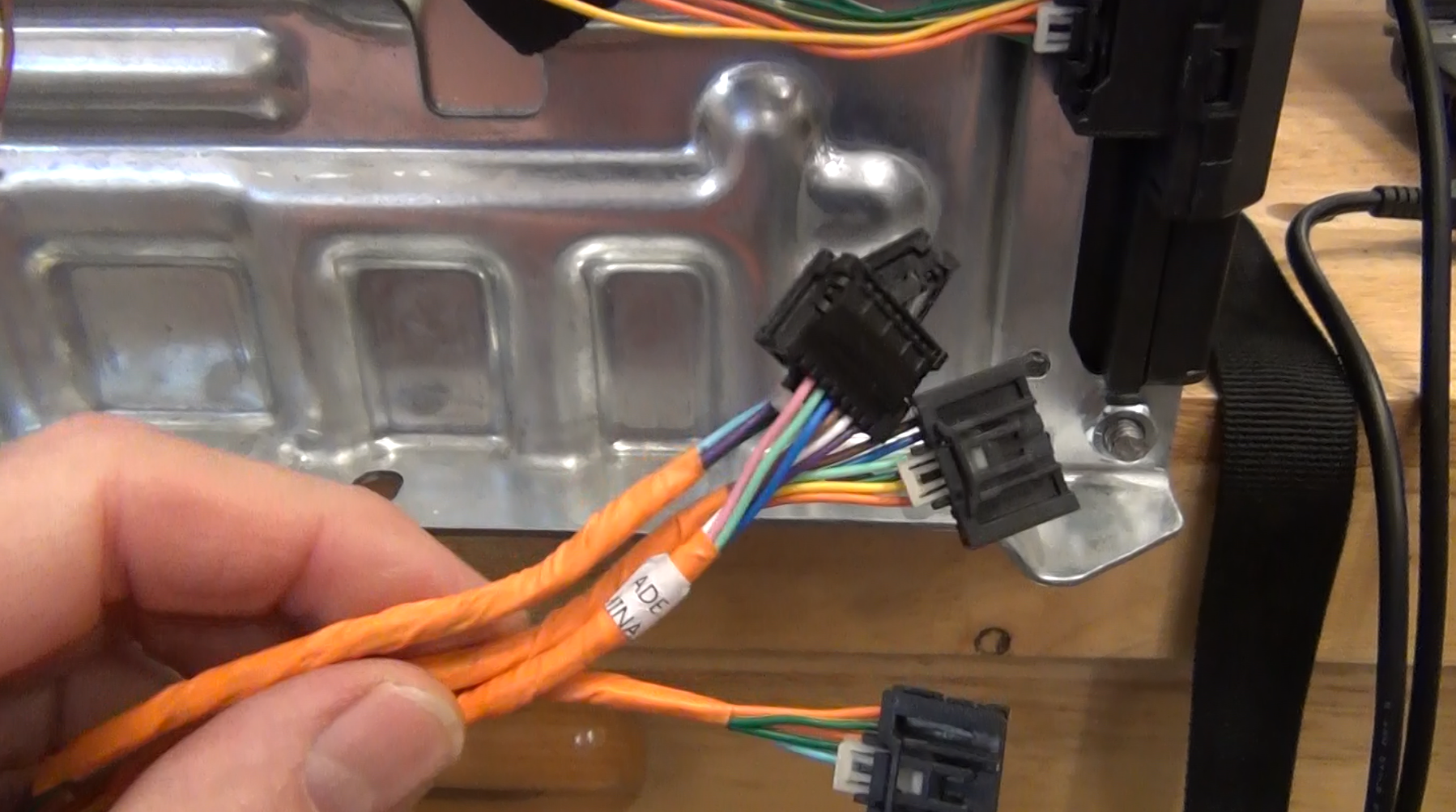
Two connectors are required to connect to all the battery cells in the module. A DB25 connector is used for the wires coming from the battery module to make connection the BMS demo board because the demo board is only supplied with screw connectors. The DB25 was installed to enable the test of all the batteries with one DC2259A Demo board.
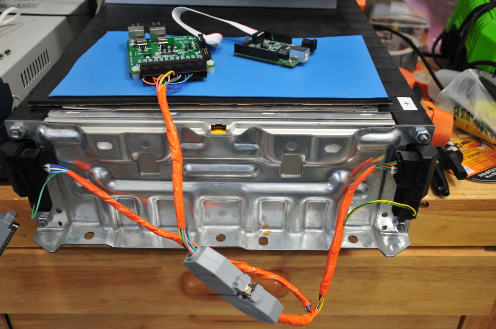
DC2259A BMS demo board that demonstrates the LTC6811-1 BMS integrated circuit. It is the 48-pin integrated circuit at the center of the board.
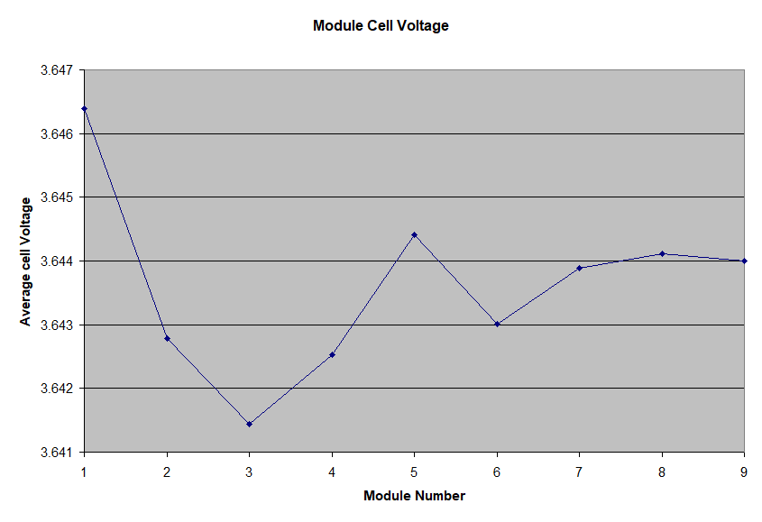
This is a plot of the average of the ten cells in each battery module that was measured with one DC2259A BMS demo board. This measurement is of the as-received modules from the factory. For effectively 90 cells the cell voltage variance is only +/- 2.5mV. If the two modules that show the largest difference we adjusted to match the other modules the variance would drop to +/- 1mV!
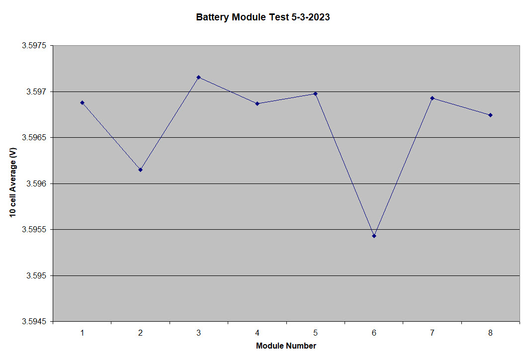
UPDATE: Below is the average cell voltage for 8 of the battery modules, measured recently. The batteries are at a different state of charge (SOC) but the cell voltage distribution is even tighter, less than +/- 1mV. The 9th battery module was not included because it is being used as a bench test platform and the battery box to house the module has not been built yet, so it is not in the car connected to the other battery modules. No adjustment of the individual battery modules was done. This is after nearly three years of charge and discharge cycles.
A video of the Chevy Bolt battery is coming soon.