Supplier Listing
Listing of the suppliers I used for my build. Download the spreadsheet here. Any of the first three suppliers can supply all the components needed for a converstion. Price and availablity are the main differneces. The other suppliers are for all the other items that are required for restoring a car or building electronics.
320i Specs and EV Design
This 320i in fantastic condition was found on Ebay. The car had been stored for more than 15 years which is why it is in such good condition. It has many features that make it any ideal doner car for an electric vehicle conversion. First, it is very light, about 2500 lbs curb weight. Second, it has lots of room for placing batteries. Third, it basically has no computer systems for controlling the car. This BMW 320i is actually a 320i"s" for sport version. It has an upgraded suspension, a limited slip differential and the seats in the passenger compartment are "Recaro" seats - very tight bucket seat. Here is the link on Wikipedia for the 320 series.
Proform Vehicle Scale weight distribution after ICE component removal:
Left front = 403 lbs; Right front = 363 lbs Total = 766 lbs
Left rear = 509 lbs; Right rear = 502 lbs Total = 1011 lbs
Total weight = 1776 lbs, so based on a curb weight of 2452 lbs that means 675 lbs for the ICE components. Probably not all that weight just off the front end. Some weight was for the gas tanks and exhaust and drive shaft.
Battery placement
18 cells in front between wheel wells = 80 lbs
Siemens motor and DMOC 645 = 320 lbs
48 cells under rear seat = 213 lbs
54 cells in trunk, over the rear axle = 240 lbs
Brusa charger in trunk = 13 lbs
Front added weight = 80 + 320 = 400 lbs
Rear added weight = 213 + 240 + 13 = 466 lbs
Front will also have water heating and cooling, brake vacuum and DC-DC converters, that will be at least 60 lbs and some of the battery weight under the rear seat will probably translate to the front wheels.
Just the batteries and motor and components weight added to the de-ICE weight gives 2642 lbs. The transmission, clutch and drive shaft weigh 108 lbs. Of course the battery boxes will add weight. The total conversion weight still should be well under 3000 lbs.
Post build note: weight is 2860 lbs with a 48/52 front/rear weight ratio.
Here is the design layout of most of the components for the engine compartment.
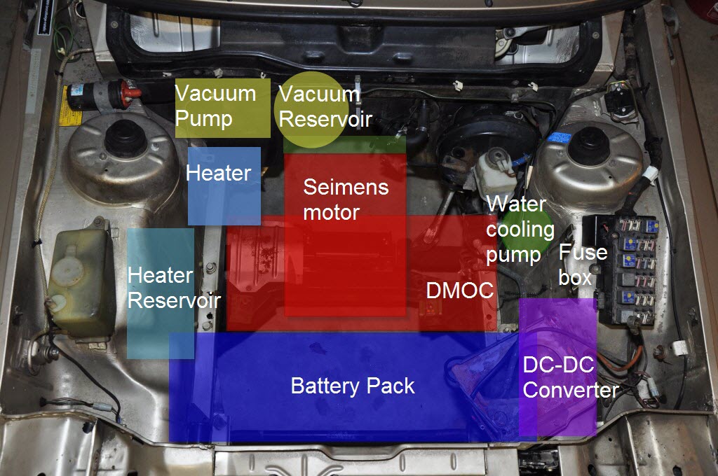
On an EV electric motors have to provide resources like heating and vacuum that were available on the ICE. So there is a vacuum pump and reservoir for the brakes and cabin controls and a heating unit and reservoir for the fluid to heat the cabin. The Siemens drive motor does not need much cooling, but the DMOC inverter does need to be cooled. So there is a pump and heat exchanger. The heat exchanger is a small radiator and it will sit directly behind the front grill. The radiator needs a fan for when the vehicle is not moving. The 320i has a fan that was intended to cool the evaporator coil for the air conditioning, even though there is no air conditioning on the car. But I found that the fan draws 25 Amps! A heat exchanger from Derale will be used instead. It only draws 5 to 6 Amps.
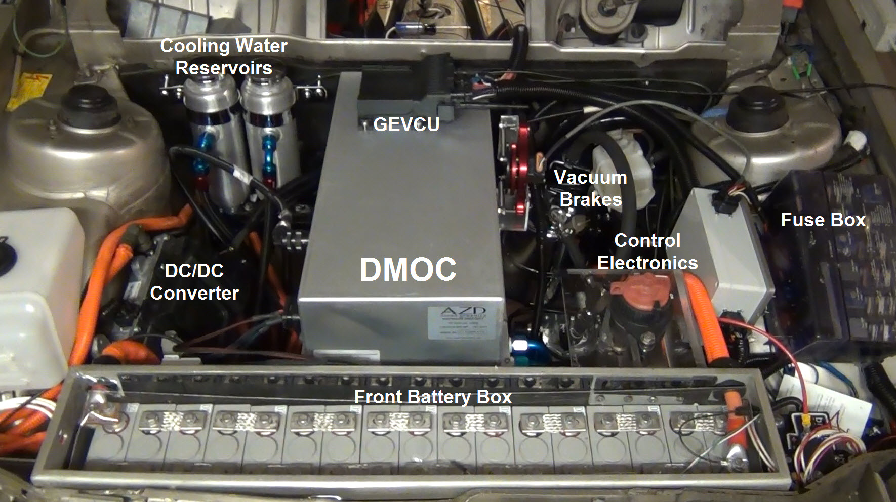
Below is how the actual build looks like. The Siemens motor is below the DMOC so it cannot be seen. Water pumps are also below as well as the main contactor box. There is no heating reservoir as I am using PTC heater elements to heat the passenger compartment.
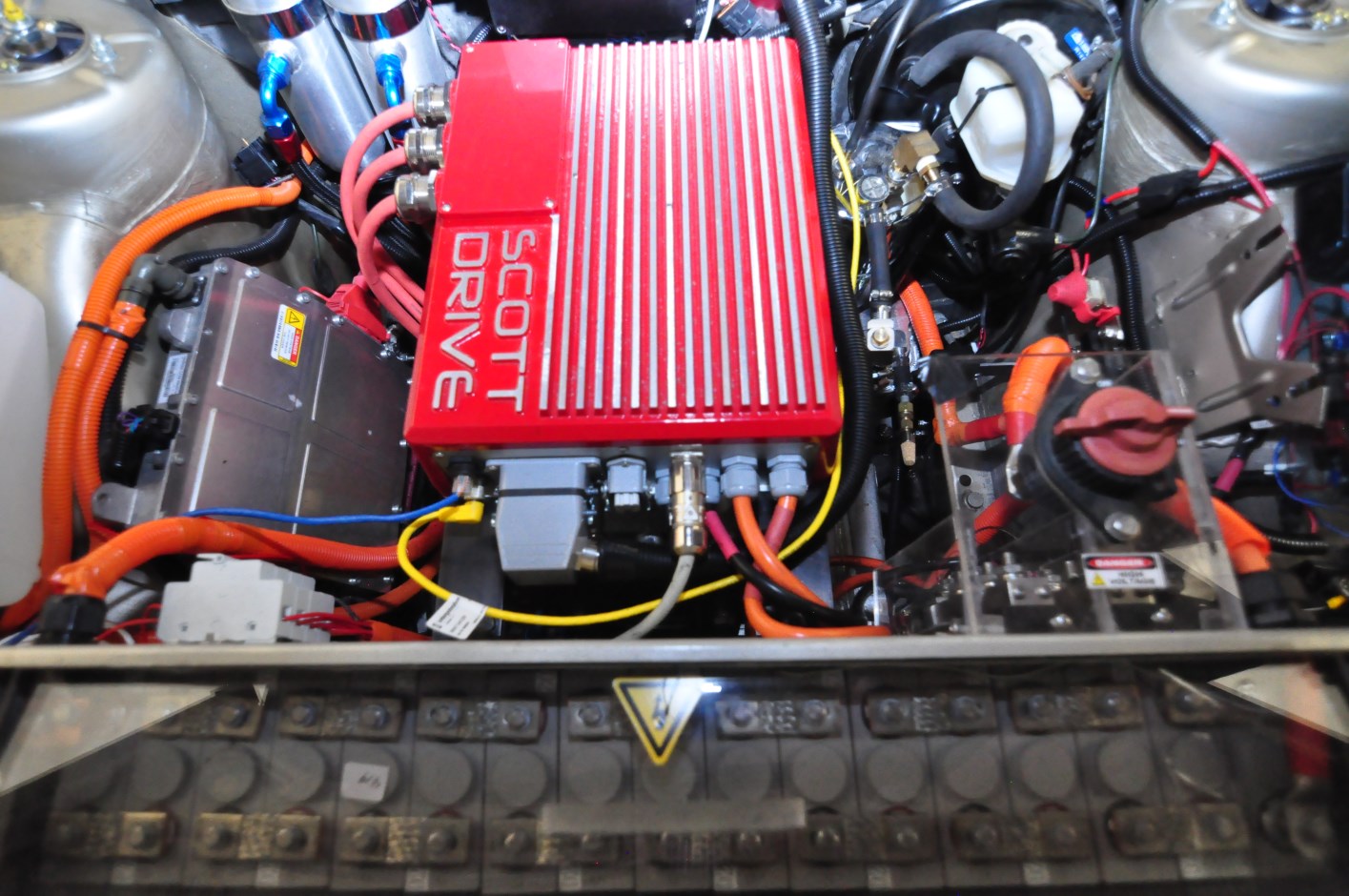
Below is the latest upgrade. The DMOC and GEVCU were replaced with a Scott Drive controller system. The Control Electronics have also been removed as all that functionality is contained in the Scott Drive.
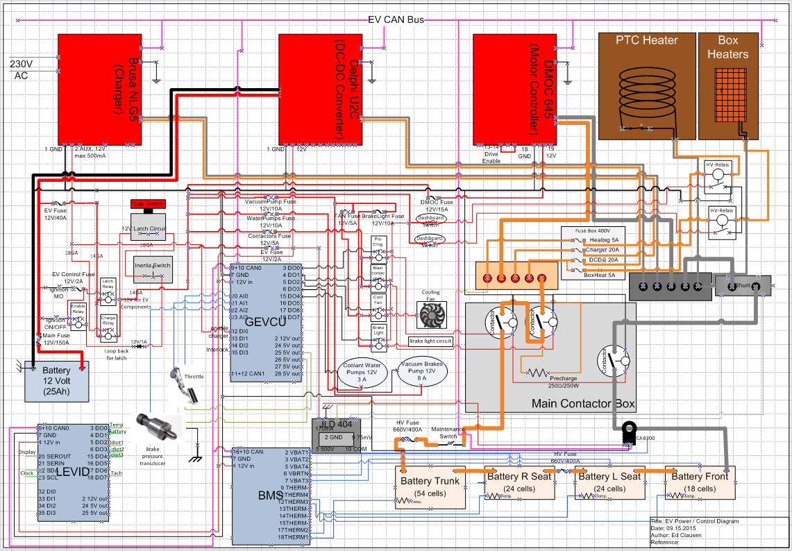
Below is the wiring schematic for the complete design. A larger view of this diagram can be seen in the photogallery.
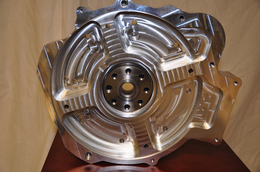
I plan to use the 5-speed manual transmission from the 320i for the EV build. That will be used with a racing clutch from Summit Racing. A high torque clutch is required because of all the torque the electric motor generates at zero RPM. If the clutch is not strong enough the vehicle might not even move and the clutch will just spin and burn. The clutch and flywheel will be spin balanced together. That is done to reduce drivetrain vibrations which are very noticeable in a electric drive vehicle because the motor does not vibrate like an ICE. The balancing is being done by a local company called Lindskog Balancing. The 5-speed transmission will be coupled to the Siemens motor using a bell housing adpater made by RebirthAuto and a spline adapter made by EV West shown below. The adapter connects the spline drive shaft of the electic motor to the flywheel, clutch and transmission. The clutch side is shown.
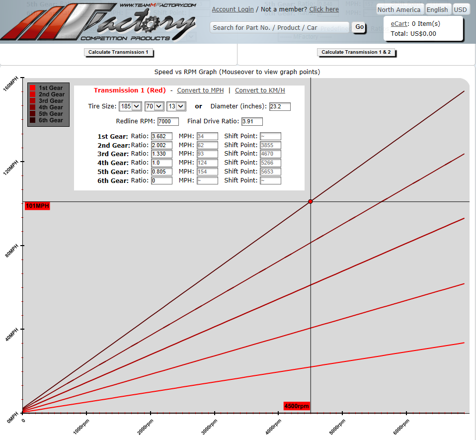
On the 2/7/2014 issue of the Vblog at EVTV there was a discussion of gear ratios, RPM and speed. Below is a graph of the calculated speed as a function of RPM for the 320i with the current gear ratios and tires. It shows that at 4500 RPM in 5th gear the 320i should be capable of over 100 MPH. This graph is from TeammFactory.com
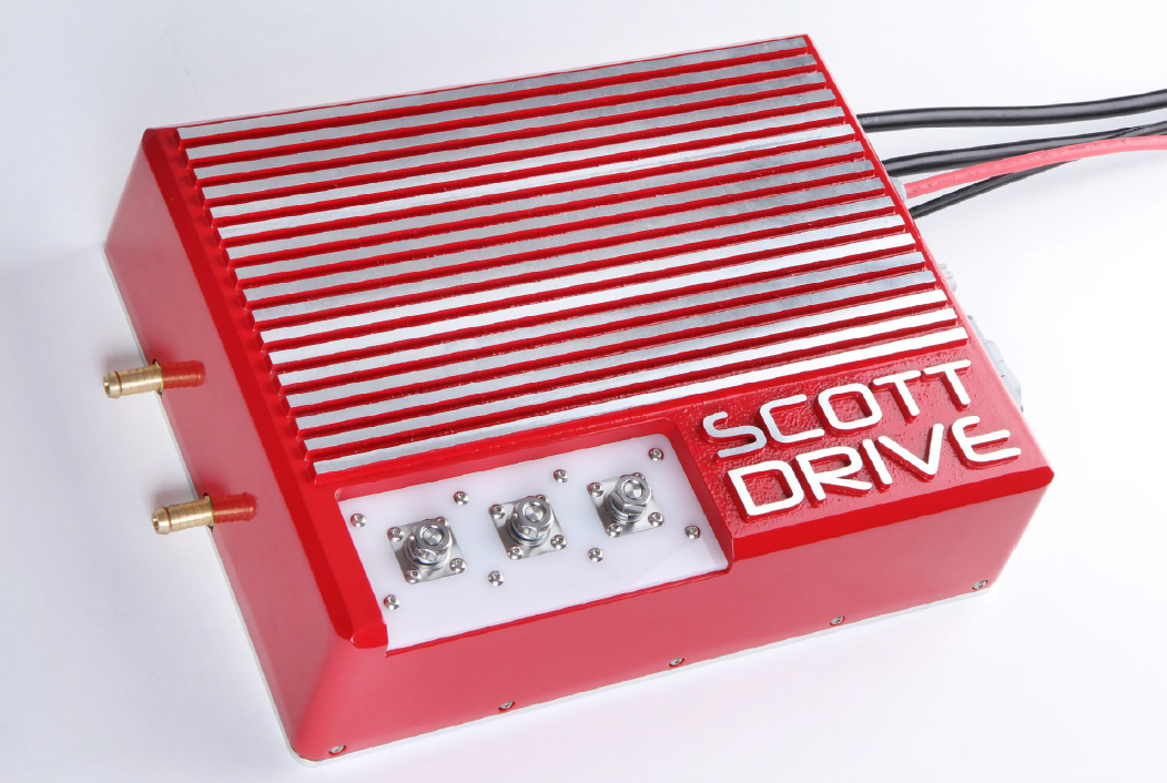
Scott Drive SD100
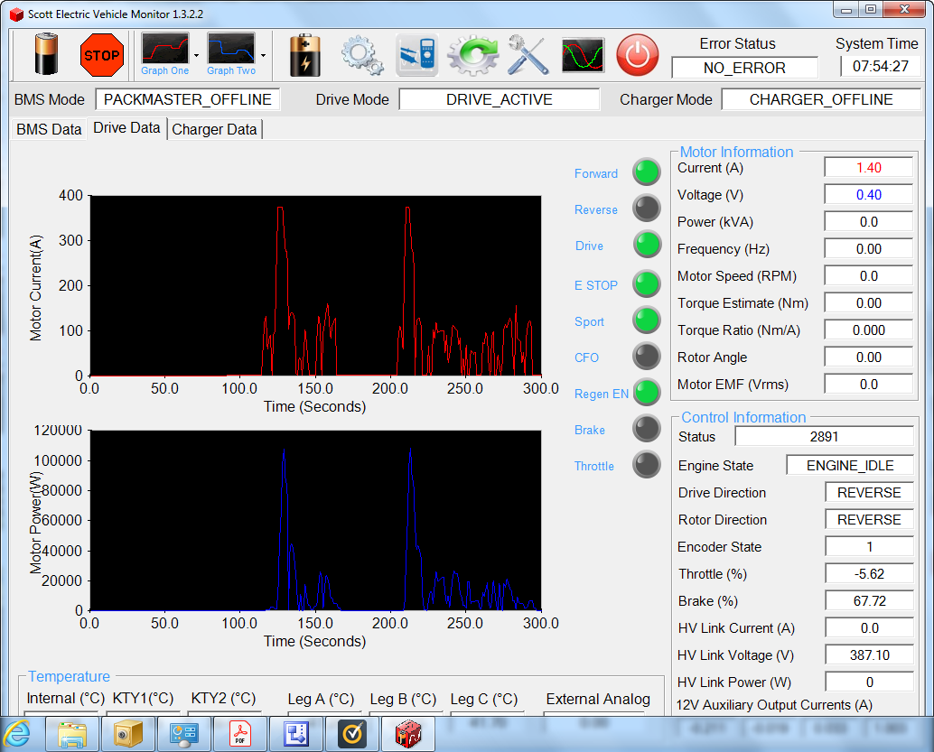
Although I was one of the initial designers of the GEVCU (see EV Design), the combination of the GEVCU and the DMOC proved to be too unreliable. After I finished the conversion and started driving the car, several times the GEVCU will fail to operate. My experience was not unique - other GEVCU users had similar problems. Fortunately for me I was never stranded anywhere when the GEVCU failed, either in my garage or driveway. But I was concerned that I would be stranded somewhere as I was using the car for a semi daily driver. I wanted a more reliable, commercial system. Several years ago I reviewed a Scott Drive SD100 inverter at EVWest. I purchased that inverter and in 2019 I installed it in the car. It took about 4 months to install. I had to make a completely new wiring harness for the control signals, modify the plumbing for the water cooling and build a new mounting system. Initially it did not work correctly. It would turn the Siemens motor in reverse. The software GUI shown below had a setting that you could change the motor direction with, but the software would crash every time that setup was saved. It turned out the Scott Drive needed a firmware update that I had to get from Scott Osborne in New Zealand, the maker of Scott Drive. Once that was taken care of the inverter worked as advertised. It is a 100KW inverter so it matches the Siemens motor well. It has a large number of inputs and control signals available. Just like the GEVCU it has the ability to put the motor in regeneration for braking. If you want to learn more about the SD100 and other Scott Drive inverters you can find that here.
Software GUI used to setup, calibrate and monitor the Scott Drive. If connected to a laptop during driving the performance data can be captured as shown below. Although the inverter is capable of 100KW continuously it is also capable of up to 150KW peak.
Rinehart Inverter PM100DX
I replaced the DMOC/GEVCU inverter and controller with a Scott Drive SD100 as noted above because the GEVCU controller was having reliability issues. The Scott Drive proved to be very reliable once the setup was completed. The SD100 has many great features, including a built-in precharge circuit and isolation switch. It provides all the CAN message for the motor performance and has a GUI for setup, calibration and control. The SD100 showed much better reliability and seemed to perform well - i.e. the car seemed to accelerate well. Something that I never did for the DMOC/GEVCU setup was to run the car on a dynamometer to measure the power and torque output. The only benchmark for the DMOC/GEVCU - Siemens motor setup was in a 1978 VW Thing, that was measured to have 160HP and 221 ft-lb of torque. Last summer I found a nearby shop that had several dynamometers and was able to get the 320e tested with the Scott Drive. I was not expecting a great result as I had measured that the Scott Drive was outputting high power, but only for 3 seconds. You can see that in the capture of the GUI screen for the SD100 above. It shows the current and power vs time, but the peaks are very narrow. That is hardly enough time to accelerate the car, although it is something you can definitely feel in the seat of you pants. Unfortunately, the SD100 really is not accelerating the car and was such a problem when testing on the dynamometer that in first gear the wheels would not even turn. The car would just lurch on its suspension and then settle. The Scott Drive shuts down the current to less than half of full current after 3 seconds, even with the accelerator pedal pressed to the floor. The best HP/Torque curve was obtained in 3rd gear, but very is disappointing. See the graph below.
Power torque curve for the 320e in third gear with the SD100.The max power is 128HP and the max torque only 110ft-lb.
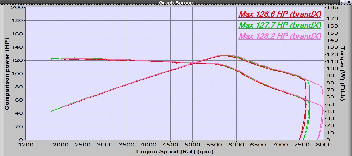
This poor power/torque performance was expected based on how the current shuts down from the inverter. There is no adjustment on that parameter, it is built into the firmware. I think Scott Drive does not know how to use their inverters in a car application. The only data I had seen from them was bench testing. That provides a minimal look at the performance. But it seem like their only goal is to over protect the Integrated Gate Bipolar Transistors (IGBT)s. There is no warranty on this inverter. It is more than 6 years old, so why should Scott Drive care how hard I drive the IGBTs? This issue is what convinced me to change to a Rinehart Inverter. The first parameter I looked at for the Rinehart was the current – time limit. Cascadia Motion (who own Rinehart) say in their documentation to limit the full current of 350Amp RMS to less than 30 seconds!! Also, from the documentation is seems like most of the firmware is open – i.e., most of the parameters are adjustable. This should work much better for driving the 320e and the documentation for the Rinehart shows that Scott Drive is wrong about driving IGBTs. The small downside of the Rinehart is there is no GUI for setup and calibration. Those values all have to be entered into the firmware via a GUI with a command line interface. Below is an image of the Rinehart PM100PX inverter.
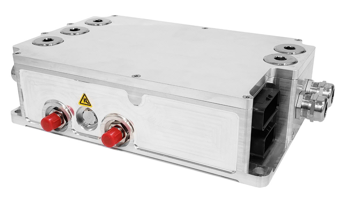
All of the high current DC and AC wires and the water lines are the same as the SD100. The biggest difference is the analog and logic connections to the controller. The PM100DX has Ampseal 35pin and Ampseal 23pin connectors for all those functions. Ampseal is actually an easier connector to work with than what was on the SD100 and most of the car uses Ampseal connectors. But I had to build a whole new wiring harness and changed most of the wire crossover box connections. The PM100DX is a different size than the SD100 so I had to cut some aluminum plates to make an adapter to the DMOC frame, that sits on top of the Siemens motor. Control of the Rinehart is very similar to the SD100, the major difference is the logic reference. For the SD100 logic was positive (i.e. +5V switching) but on the Rinehart the logic is ground switching. To use the same wires I already had installed in the glove box I had to verify that all the logic wires were isolated so I could just swap the connections. The only wire I had a problem with was the USB connector for phone charging. I had to grab a +12V and ground from under the dash to power that connection.
Unfortunately after spending months on trying to get the Rinehart to work, the inverter failed catastrophically. Check out the article below that is also in the Blog.
Rinehart Inverter Failure
This inverter has been very much a problem from the beginning. Mechanically it was very easy to install, to get it mounted on the same mount as the Scott Drive, connected to coolant and connected to all the low and high voltage lines without any issues. But electrically and programmatically it has been problematic. First, I had to create a completely new wiring harness because the Rinehart uses Ampseal connectors and the inverter I replaced used Epic. The motor encoder control signals were also on an Ampseal connector so I had to build interface to the encoder cable that has Sealcon M23 round connectors. Even the cross-over box that I used to break out the wires had to be significantly changed and new wires had to be run for more control. I found that the inverter requires a very specific set of conditions of connections and firmware settings to be met so that it will enable the output. What makes the Rinehart great is that I had access to every firmware value that affects the opertion of the car. But that is also what makes it difficult. Even after working over the past month all the conditions still were not satisfied to enable torque output. The inverter shows that is enabled and in Run mode, but nothing happens when the accelerator is pressed. I have been getting support from Cascadia Motion and working through the issues. They discovered reviewing the output from the firmware listing is that the Hardware (HW) version had changed. That is not possible outside the factory so some transient in the system corrupted the EEPROM memory. They thought that updating the firmware may fix the inverter issues. Updating firmware in an inverter is not a new thing for me, I had to do that on both the Scott Drive and DMOC. For the Rinehart it just required the serial interface and the connection to the Software upload enable pin. I was preparing to do the firmware update, I had gotten all the connections I needed, but when I turned the car off to make the connections, I hear a loud bang and I could see the Rinehart visibly shake (I could feel it in the car too). There are no mechanical switches in the Rinehart so that noise could only be a large electrical discharge inside the unit. I tried to turn the car on, but the main contactors would not close. Those are now controlled by the Rinehart. I discovered that the 12V 5-amp fuse to the Rinehart was blown. I replaced the fuse, but when I turned the car on it blew it again. I measured the input impedance for the 12V into the Rinehart and it is several mega ohms so this is a semiconductor short – when the circuit is energized it draws too much current. I checked with the support from Cascadia Motion and they said a 10-amp fuse would be okay, but I found after a few minutes the inverter would blow that one too. It was after the 10-amp fuse blew that I could smell the familiar smell of burnt electronics. So now the Rinehart is probably bricked. Cascadia Motion does have an RMA and repair service. They charge $650 to evaluate the unit and give you a quote for repair. The problem will be what actually failed. Was it just the controller board or did one or more of the IGBT transistors blow too? Something had a large electrical breakdown to make the unit move and create that loud bang. I requested and received an RMA, but I will have to think about if I even want to know what went wrong. If it is something major the repair could be as much as a new unit. That unit won’t even turn on with is not promising and the $650 could be just a waste of money. I removed the inverter from the car, it had to be cleaned of cooling fluid and the inlets capped, in case I decide to send it back to Cascadia Motion. While I had It out, I put it on my test bench. With a DC power supply that was only 40W I was able to turn the inverter on. It drew more current when it started up and pulled the voltage down on the supply but that only lasted a second or two. When it settled it was only drawing 650mA. I was able to connect to it with the RS-232 and using their GUI I found that it now showed multiple hardware failures. And the HW version had changed again. I took a screen shot of that and sent it off to Cascadia Motion support. From those faults they said it’s most likely the power module (IGBT), potentially the gate drive board too, but not the control card and not likely the IO board. The repair could be somewhere between about $1500-$2500, but I would know without sending the unit back. The timing is also an issue. The RMA request said that process of evaluation my take 4 - 6 weeks and the repair could be twice that, even longer if they do not have the spare parts. Since the Rinehart is now removed from the car I went ahead and put the Scott Drive back in because I would like to drive the car now the seasons have changed. I had retained the wiring harness and mechanically did not alter the engine bay so it dropped right in. I did not even change the cooling lines. I had bought all new hardware because Rinehart uses AN fittings and the Scott Drive is barb hose fittings, but I never got a chance to change the fittings. The Scott Drive uses many fewer inputs than the Rinehart so it only took a day to rewire the cross-over box. I started up the Scott Drive and run the Scott Drive GUI. The throttle and brake seemed to still be calibrated with the offset and gain that was in firmware and the motor spun right up when the accelerator was pressed. The regen even slowed the motor spin down with the application of the brakes. I just have to clean up the connections inside the car and then I will be able to take the 320e for a test drive. I will post another blog after I decide what I am going to do with the Rinehart.
Page 1 of 3